IOS XRvでMPBGPな普通のMPLS L3VPNとSegment Routing
Posted on 2015/06/09(Tue) 23:55 in technical
サマリ
いつぞや、 Ubuntu DesktopにGNS3 1.3.1を入れてXRvを起動 できることを確認しました。
今回は、比較的昔から実装されているL3VPNを構成します。
でも足回りは前回 IOS XRvではじめてのIS-IS Segment Routing で使ったSegment Routingと組み合わせて構成してみます。
やっぱりSegment Routingで配布したラベルと組み合わせてこそだよね。と言うわけで、れっつごー。
ちなみに、特に理由はありませんがGNS3 1.3.4にアップグレード済みです。
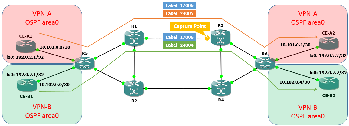
NW構成
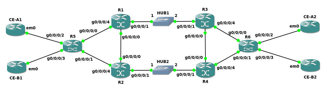
HUB1とHUB2は、その地点でキャプチャを取得するために置かれています。
警告
GNS3 1.3.4になっても、KVM同士の直結リンクをキャプチャ出来ないのです。
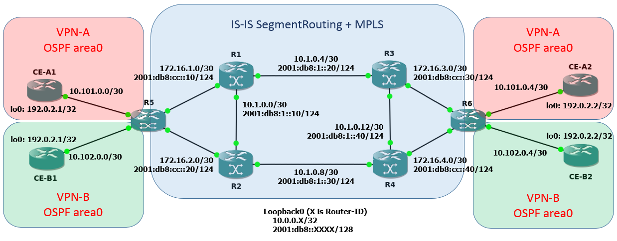
アドレス構成は大体こんな感じ。インタフェースのアドレスは数字の小さいルータから数字を割り当てていきます。
10.1.0.0/30の時、R1は10.1.0.1、R2は10.1.0.2と言う感じ。
将来的にIPv6をネタにするかもしれないから、と言う漠然とした理由でIPv6に関する設定が含まれていますが、基本使わないので無視しても問題ありません。
通報
GNS3のトポロジをKVMで構成する場合、プロジェクト内に差分ディスクが保存されます。なので、途中でプロジェクトを停止してもコンフィグは残ります。
逆に、トポロジを維持したままコンフィグだけクリアしたい場合は、:
$ rm -rf <project-directory>/project-files/qemu/*
とすれば良いので、良く分からなくなったらとりあえず消して一からやるのも手です。
ただ、XRvに関しては一般的なIOS XRのコンフィグ管理手順を使用することが出来るので、例えば:
#copy running-config config-backup.cfg
のように保存し、:
#dir usr
Tue Jun  8 15:26:07.871 UTC

Directory of disk0:/usr

63526       -rwx  2696        Tue Jun  8 15:23:26 2015  config-backup.cfg

2377105408 bytes total (1868198912 bytes free)
#configure
(config)#load usr/config-backup.cfg
(config)#commit replace
として任意のコンフィグと入れ替えることができますし、コンフィグマネージメントは自分に合った方法でお願いします。
初期コンフィグレーション
まずは前回同様、IS-ISによるコア網内のルーティングを設定してしまいます。
整理がてら書いているだけなので、ここは飛ばしても良いでしょう。
警告
行数削減のために一部ネストしていない表記が混じっていますが、上手く解釈してください。
R1:
configure
hostname R1
interface Loopback0
 ipv4 address 10.0.0.1/32
 ipv6 address 2001:db8::1111/128
interface GigabitEthernet0/0/0/0
 ipv4 address 10.1.0.1/30
 ipv6 address 2001:db8:1::11/124
 no shut
interface GigabitEthernet0/0/0/1
 ipv4 address 10.1.0.5/30
 ipv6 address 2001:db8:1::21/124
 no shut
interface GigabitEthernet0/0/0/4
 ipv4 address 172.16.1.1/30
 ipv6 address 2001:db8:cc::11/124
 no shut
router isis 1
 is-type level-2-only
 net 49.0000.0000.0000.0001.00
 address-family ipv4 unicast
  metric-style wide
  segment-routing mpls
 interface Loopback0
  address-family ipv4 unicast
   prefix-sid index 1001
 interface GigabitEthernet0/0/0/0 address-family ipv4 unicast
 interface GigabitEthernet0/0/0/1 address-family ipv4 unicast
 interface GigabitEthernet0/0/0/4 address-family ipv4 unicast
 commit
end
R2:
configure
hostname R2
interface Loopback0
 ipv4 address 10.0.0.2/32
 ipv6 address 2001:db8::2222/128
interface GigabitEthernet0/0/0/0
 ipv4 address 10.1.0.2/30
 ipv6 address 2001:db8:1::12/124
 no shut
interface GigabitEthernet0/0/0/1
 ipv4 address 10.1.0.9/30
 ipv6 address 2001:db8:1::31/124
 no shut
interface GigabitEthernet0/0/0/4
 ipv4 address 172.16.2.1/30
 ipv6 address 2001:db8:cc::21/124
 no shut
router isis 1
 is-type level-2-only
 net 49.0000.0000.0000.0002.00
 address-family ipv4 unicast
  metric-style wide
  segment-routing mpls
 interface Loopback0
  address-family ipv4 unicast
   prefix-sid index 10002
 interface GigabitEthernet0/0/0/0 address-family ipv4 unicast
 interface GigabitEthernet0/0/0/1 address-family ipv4 unicast
 interface GigabitEthernet0/0/0/4 address-family ipv4 unicast
 commit
end
R3:
configure
hostname R3
interface Loopback0
 ipv4 address 10.0.0.3/32
 ipv6 address 2001:db8::3333/128
interface GigabitEthernet0/0/0/0
 ipv4 address 10.1.0.13/30
 ipv6 address 2001:db8:1::41/124
 no shut
interface GigabitEthernet0/0/0/1
 ipv4 address 10.1.0.6/30
 ipv6 address 2001:db8:1::22/124
 no shut
interface GigabitEthernet0/0/0/4
 ipv4 address 172.16.3.1/30
 ipv6 address 2001:db8:cc::31/124
 no shut
router isis 1
 is-type level-2-only
 net 49.0000.0000.0000.0003.00
 address-family ipv4 unicast
  metric-style wide
  segment-routing mpls
 interface Loopback0
  address-family ipv4 unicast
   prefix-sid index 1003
 interface GigabitEthernet0/0/0/0 address-family ipv4 unicast
 interface GigabitEthernet0/0/0/1 address-family ipv4 unicast
 interface GigabitEthernet0/0/0/4 address-family ipv4 unicast
 commit
end
R4:
configure
hostname R4
interface Loopback0
 ipv4 address 10.0.0.4/32
 ipv6 address 2001:db8::4444/128
interface GigabitEthernet0/0/0/0
 ipv4 address 10.1.0.14/30
 ipv6 address 2001:db8:1::14/124
 no shut
interface GigabitEthernet0/0/0/1
 ipv4 address 10.1.0.10/30
 ipv6 address 2001:db8:1::a/124
 no shut
interface GigabitEthernet0/0/0/4
 ipv4 address 172.16.4.1/30
 ipv6 address 2001:db8:cc::41/124
 no shut
router isis 1
 is-type level-2-only
 net 49.0000.0000.0000.0004.00
 address-family ipv4 unicast
  metric-style wide
  segment-routing mpls
 interface Loopback0
  address-family ipv4 unicast
   prefix-sid index 1004
 interface GigabitEthernet0/0/0/0 address-family ipv4 unicast
 interface GigabitEthernet0/0/0/1 address-family ipv4 unicast
 interface GigabitEthernet0/0/0/4 address-family ipv4 unicast
 commit
end
R5:
configure
hostname R5
interface Loopback0
 ipv4 address 10.0.0.5/32
 ipv6 address 2001:db8::5555/128
interface GigabitEthernet0/0/0/0
 ipv4 address 172.16.1.2/30
 ipv6 address 2001:db8:cc::12/124
 no shut
interface GigabitEthernet0/0/0/1
 ipv4 address 172.16.2.2/30
 ipv6 address 2001:db8:cc::22/124
 no shut
router isis 1
 is-type level-2-only
 net 49.0000.0000.0000.0005.00
 address-family ipv4 unicast
  metric-style wide
  segment-routing mpls
 interface Loopback0
  address-family ipv4 unicast
   prefix-sid index 1005
 interface GigabitEthernet0/0/0/0 address-family ipv4 unicast
 interface GigabitEthernet0/0/0/1 address-family ipv4 unicast
 commit
end
R6:
configure
hostname R6
interface Loopback0
 ipv4 address 10.0.0.6/32
 ipv6 address 2001:db8::6666/128
interface GigabitEthernet0/0/0/0
 ipv4 address 172.16.3.2/30
 ipv6 address 2001:db8:cc::12/124
 no shut
interface GigabitEthernet0/0/0/1
 ipv4 address 172.16.4.2/30
 ipv6 address 2001:db8:cc::22/124
 no shut
router isis 1
 is-type level-2-only
 net 49.0000.0000.0000.0006.00
 address-family ipv4 unicast
  metric-style wide
  segment-routing mpls
 interface Loopback0
  address-family ipv4 unicast
   prefix-sid index 1006
 interface GigabitEthernet0/0/0/0 address-family ipv4 unicast
 interface GigabitEthernet0/0/0/1 address-family ipv4 unicast
 commit
end
MPLS L3VPNの設定
まず、コア網内でiBGP網を構成(今回はR1とR4をRoute-Reflectorとして設定)
R1, R4:
configure
router bgp 65000
 address-family ipv4 unicast
 address-family ipv6 unicast
 address-family vpnv4 unicast
 address-family vpnv6 unicast
 neighbor-group CORE
  remote-as 65000
  update-source Loopback0
  address-family ipv4 unicast route-reflector-client
  address-family ipv6 unicast route-reflector-client
  address-family vpnv4 unicast route-reflector-client
  address-family vpnv6 unicast route-reflector-client
  exit
 neighbor 10.0.0.1 use neighbor-group CORE
 neighbor 10.0.0.2 use neighbor-group CORE
 neighbor 10.0.0.3 use neighbor-group CORE
 neighbor 10.0.0.4 use neighbor-group CORE
 neighbor 10.0.0.5 use neighbor-group CORE
 neighbor 10.0.0.6 use neighbor-group CORE
 commit
end
R2, R3, R5, R6:
configure
router bgp 65000
 address-family ipv4 unicast
 address-family ipv6 unicast
 address-family vpnv4 unicast
 address-family vpnv6 unicast
 neighbor-group CORE
  remote-as 65000
  update-source Loopback0
  address-family ipv4 unicast route-reflector-client
  address-family ipv6 unicast route-reflector-client
  address-family vpnv4 unicast route-reflector-client
  address-family vpnv6 unicast route-reflector-client
  exit
 neighbor 10.0.0.1 use neighbor-group CORE
 neighbor 10.0.0.4 use neighbor-group CORE
 commit
end
次に、VRFを作成し、Interfaceへ適用。
R5:
configure
 vrf VRF-A address-family ipv4 unicast import route-target 65000:101
 vrf VRF-A address-family ipv4 unicast export route-target 65000:101
 vrf VRF-A address-family ipv6 unicast import route-target 65000:101
 vrf VRF-A address-family ipv6 unicast export route-target 65000:101
 vrf VRF-B address-family ipv4 unicast import route-target 65000:102
 vrf VRF-B address-family ipv4 unicast export route-target 65000:102
 vrf VRF-B address-family ipv6 unicast import route-target 65000:102
 vrf VRF-B address-family ipv6 unicast export route-target 65000:102
 interface GigabitEthernet0/0/0/2
  vrf VRF-A
  ipv4 address 10.101.0.1/30
  ipv6 address 2001:db8:101::11/124
  no shutdown
 interface GigabitEthernet0/0/0/3
  vrf VRF-B
  ipv4 address 10.102.0.1/30
  ipv6 address 2001:db8:102::11/124
  no shutdown
  commit
end
R6:
configure
 vrf VRF-A address-family ipv4 unicast import route-target 65000:101
 vrf VRF-A address-family ipv4 unicast export route-target 65000:101
 vrf VRF-A address-family ipv6 unicast import route-target 65000:101
 vrf VRF-A address-family ipv6 unicast export route-target 65000:101
 vrf VRF-B address-family ipv4 unicast import route-target 65000:102
 vrf VRF-B address-family ipv4 unicast export route-target 65000:102
 vrf VRF-B address-family ipv6 unicast import route-target 65000:102
 vrf VRF-B address-family ipv6 unicast export route-target 65000:102
 interface GigabitEthernet0/0/0/2
  vrf VRF-A
  ipv4 address 10.101.0.5/30
  ipv6 address 2001:db8:101::21/124
  no shutdown
 interface GigabitEthernet0/0/0/3
  vrf VRF-B
  ipv4 address 10.102.0.5/30
  ipv6 address 2001:db8:102::21/124
  no shutdown
  commit
end
収容ユーザの接続方式に合わせて、VRF毎にルーティングの設定(今回はOSPF)。
R5:
configure
 router ospf 1
  router-id 10.0.0.5
  vrf VRF-A redistribute bgp 65000
  vrf VRF-A area 0 interface gigabitEthernet0/0/0/2
  vrf VRF-B redistribute bgp 65000
  vrf VRF-B area 0 interface gigabitEthernet0/0/0/3
 router bgp 65000
  vrf VRF-A
   rd 65000:101
   address-family ipv4 unicast
     redistribute ospf 1
   address-family ipv6 unicast
  vrf VRF-B
   rd 65000:102
   address-family ipv4 unicast
     redistribute ospf 1
   address-family ipv6 unicast
   commit
end
R6:
configure
 router ospf 1
  router-id 10.0.0.6
  vrf VRF-A redistribute bgp 65000
  vrf VRF-A area 0 interface gigabitEthernet0/0/0/2
  vrf VRF-B redistribute bgp 65000
  vrf VRF-B area 0 interface gigabitEthernet0/0/0/3
 router bgp 65000
  vrf VRF-A
   rd 65000:101
   address-family ipv4 unicast
     redistribute ospf 1
   address-family ipv6 unicast
  vrf VRF-B
   rd 65000:102
   address-family ipv4 unicast
     redistribute ospf 1
   address-family ipv6 unicast
   commit
end
最後に、VPN収容ユーザとの接続設定
CE-A1:
# vtysh<<__EOL__
conf t
 int lo0
  ip add 192.0.2.1/32
 int em0
  ip add 10.101.0.2/30
  no shut
  exit
 router ospf
  network 10.101.0.0/30 area 0
  network 192.0.2.1/32 area 0
end
write
exit
__EOL__
CE-A2:
# vtysh<<__EOL__
conf t
 int lo0
  ip add 192.0.2.2/32
 int em0
  ip add 10.101.0.6/30
  no shut
  exit
 router ospf
  network 10.101.0.4/30 area 0
  network 192.0.2.2/32 area 0
end
write
exit
__EOL__
CE-B1:
# vtysh<<__EOL__
conf t
 int lo0
  ip add 192.0.2.1/32
 int em0
  ip add 10.102.0.2/30
  no shut
  exit
 router ospf
  network 10.102.0.0/30 area 0
  network 192.0.2.1/32 area 0
end
write
exit
__EOL__
CE-B2:
# vtysh<<__EOL__
conf t
 int lo0
  ip add 192.0.2.2/32
 int em0
  ip add 10.102.0.6/30
  no shut
  exit
 router ospf
  network 10.102.0.4/30 area 0
  network 192.0.2.2/32 area 0
end
write
exit
__EOL__
疎通確認
まずは恒例のpingとそのキャプチャ画像から。
各VPNからpingを実行:
# ping -S 192.0.2.1 192.0.2.2
で、まずはVPN-Aのキャプチャ画像
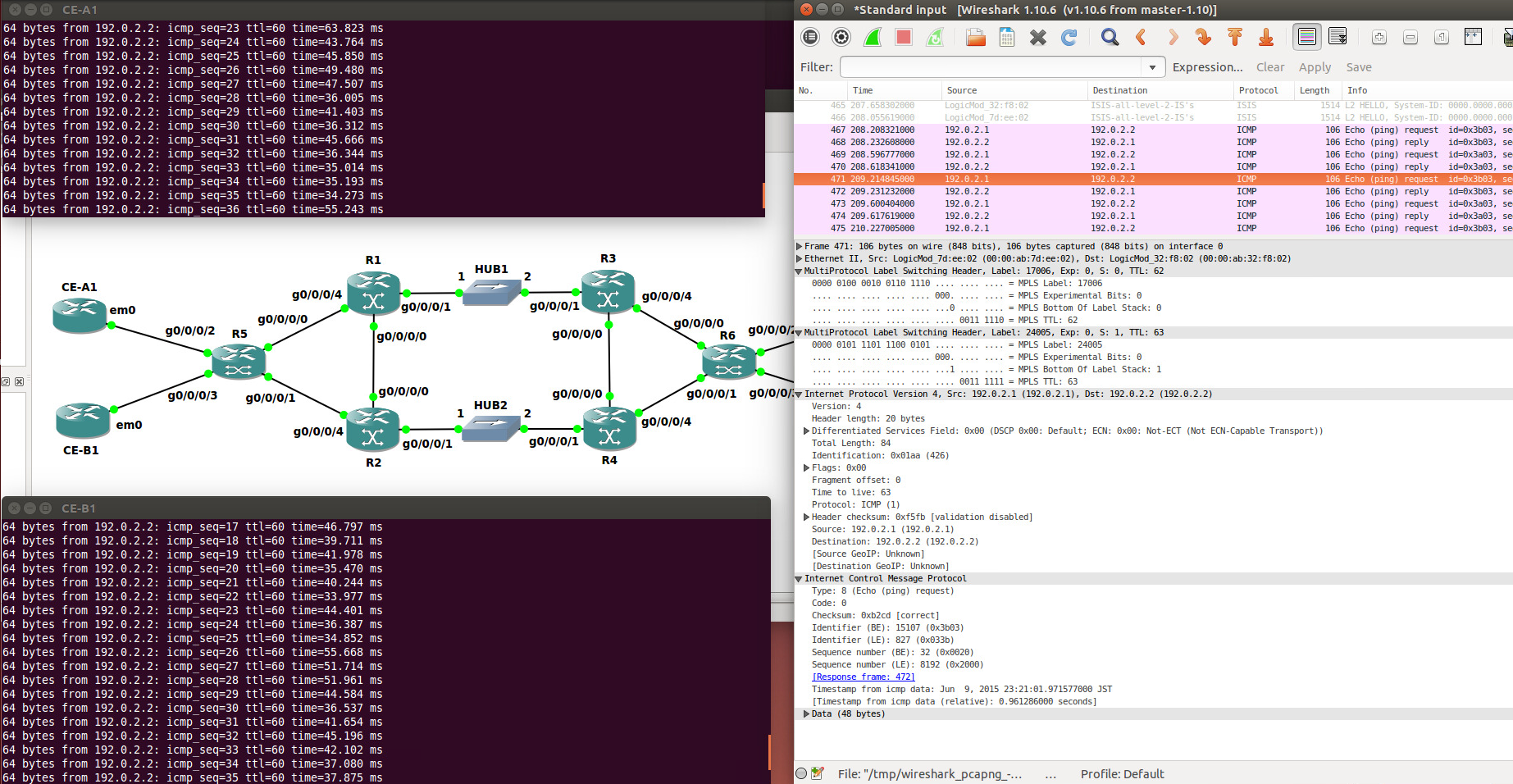
次にVPN-Bのキャプチャ画像
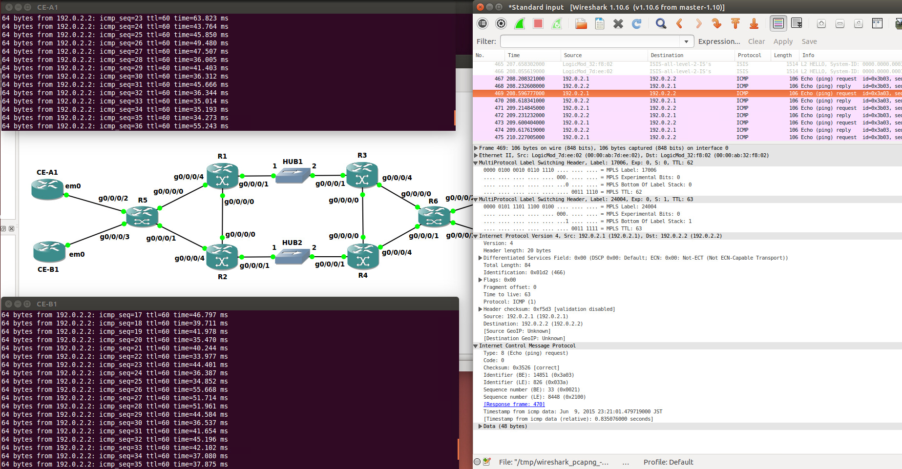
pingが混ざらずに通信出来ていて良かったね。
ちゃんとVRFラベル(24004,24005)とSRラベル(17006)が付与されていて、VPN識別ができたうえでMPLS転送が出来ていることが見て取れる。
この後テーブルを見るけど、24005がVPN-Aで24004がVPN-Bのラベル。
大体こんな感じ。
ルータの情報とか色々確認
まず、R1でMPLS転送テーブルを見ると、こんな感じになっている。:
RP/0/0/CPU0:R1#show mpls forwarding
Tue Jun  9 14:28:30.968 UTC
Local  Outgoing    Prefix             Outgoing     Next Hop        Bytes
Label  Label       or ID              Interface                    Switched
------ ----------- ------------------ ------------ --------------- ------------
17003  Pop         No ID              Gi0/0/0/1    10.1.0.6        4669
17004  17004       No ID              Gi0/0/0/0    10.1.0.2        4742
       17004       No ID              Gi0/0/0/1    10.1.0.6        0
17005  Pop         No ID              Gi0/0/0/4    172.16.1.2      20274
17006  17006       No ID              Gi0/0/0/1    10.1.0.6        1848868
24000  Pop         No ID              Gi0/0/0/0    10.1.0.2        0
24001  Pop         No ID              Gi0/0/0/1    10.1.0.6        0
24002  Pop         No ID              Gi0/0/0/4    172.16.1.2      0
MPLS網の転送先であるR5->R6は、ラベル17006(16000+1006(R6のprefix-sid index 1006))が使用される。これはIS-IS Segment Routingで学習したものだ。
更に、MPLS EdgeとなるR5のMPLS転送テーブルを見ると、VPN識別用のラベルと転送ラベルの両方を確認することが出来る。:
RP/0/0/CPU0:R5#show mpls forwarding
Tue Jun  9 14:31:28.206 UTC
Local  Outgoing    Prefix             Outgoing     Next Hop        Bytes
Label  Label       or ID              Interface                    Switched
------ ----------- ------------------ ------------ --------------- ------------
17001  Pop         No ID              Gi0/0/0/0    172.16.1.1      5862
17003  17003       No ID              Gi0/0/0/0    172.16.1.1      0
17004  17004       No ID              Gi0/0/0/1    172.16.2.1      513018
17006  17006       No ID              Gi0/0/0/0    172.16.1.1      14168
       17006       No ID              Gi0/0/0/1    172.16.2.1      2300
24000  Pop         No ID              Gi0/0/0/0    172.16.1.1      0
24001  Pop         No ID              Gi0/0/0/1    172.16.2.1      0
24002  Aggregate   VRF-A: Per-VRF Aggr[V]   \
                                      VRF-A                        2112
24003  Unlabelled  192.0.2.1/32[V]    Gi0/0/0/2    10.101.0.2      3192
24004  Aggregate   VRF-B: Per-VRF Aggr[V]   \
                                      VRF-B                        6776
24005  Unlabelled  192.0.2.1/32[V]    Gi0/0/0/3    10.102.0.2      3276
また、VRF-Aのルーティングテーブルをサンプルとして挙げると、 B 192.0.2.2/32 [200/11] via 10.0.0.6 (nexthop in vrf default) が確認でき、:
RP/0/0/CPU0:R5#show route vrf VRF-A
Tue Jun  9 14:40:04.251 UTC

Codes: C - connected, S - static, R - RIP, B - BGP, (>) - Diversion path
       D - EIGRP, EX - EIGRP external, O - OSPF, IA - OSPF inter area
       N1 - OSPF NSSA external type 1, N2 - OSPF NSSA external type 2
       E1 - OSPF external type 1, E2 - OSPF external type 2, E - EGP
       i - ISIS, L1 - IS-IS level-1, L2 - IS-IS level-2
       ia - IS-IS inter area, su - IS-IS summary null, * - candidate default
       U - per-user static route, o - ODR, L - local, G  - DAGR, l - LISP
       A - access/subscriber, a - Application route
       M - mobile route, (!) - FRR Backup path

Gateway of last resort is not set

C    10.101.0.0/30 is directly connected, 00:53:40, GigabitEthernet0/0/0/2
L    10.101.0.1/32 is directly connected, 00:53:40, GigabitEthernet0/0/0/2
B    10.101.0.4/30 [200/0] via 10.0.0.6 (nexthop in vrf default), 00:48:49
O    192.0.2.1/32 [110/11] via 10.101.0.2, 00:53:37, GigabitEthernet0/0/0/2
B    192.0.2.2/32 [200/11] via 10.0.0.6 (nexthop in vrf default), 00:21:35
その 10.0.0.6 のNextHopは 172.16.1.1 or 172.16.2.1 であり、出力時のラベルは 17006 になる(MPLS転送テーブルを見るのだ):
RP/0/0/CPU0:R5#show route 10.0.0.6/32
Tue Jun  9 14:43:17.807 UTC

Routing entry for 10.0.0.6/32
  Known via "isis 1", distance 115, metric 40, type level-2
  Installed Jun  9 14:41:16.136 for 00:02:01
  Routing Descriptor Blocks
    172.16.1.1, from 10.0.0.6, via GigabitEthernet0/0/0/0
      Route metric is 40
    172.16.2.1, from 10.0.0.6, via GigabitEthernet0/0/0/1
      Route metric is 40
  No advertising protos.
ただし、P5->P6方向に付与されるVPNラベルについては、R6から通知されたラベルを使用するので、先の画像で言う24005,24005についてはMPBGPを確認する:
RP/0/0/CPU0:R5#show bgp vpnv4 unicast labels
Tue Jun  9 14:36:37.285 UTC
BGP router identifier 10.0.0.5, local AS number 65000
BGP generic scan interval 60 secs
Non-stop routing is enabled
BGP table state: Active
Table ID: 0x0   RD version: 0
BGP main routing table version 27
BGP NSR Initial initsync version 13 (Reached)
BGP NSR/ISSU Sync-Group versions 0/0
BGP scan interval 60 secs

Status codes: s suppressed, d damped, h history, * valid, > best
              i - internal, r RIB-failure, S stale, N Nexthop-discard
Origin codes: i - IGP, e - EGP, ? - incomplete
   Network            Next Hop        Rcvd Label      Local Label
Route Distinguisher: 65000:101 (default for vrf VRF-A)
*> 10.101.0.0/30      0.0.0.0         nolabel         24002
*>i10.101.0.4/30      10.0.0.6        24002           nolabel
*> 192.0.2.1/32       10.101.0.2      nolabel         24003
*>i192.0.2.2/32       10.0.0.6        24005           nolabel
Route Distinguisher: 65000:102 (default for vrf VRF-B)
*> 10.102.0.0/30      0.0.0.0         nolabel         24004
*>i10.102.0.4/30      10.0.0.6        24003           nolabel
*> 192.0.2.1/32       10.102.0.2      nolabel         24005
*>i192.0.2.2/32       10.0.0.6        24004           nolabel

Processed 8 prefixes, 8 paths
と言う感じ。
今回はここまで
MPLS L3VPNとSegment Routingって案外動作しそうだなー、と言うのがお分かり頂けただろうか。
残るラベル制御と言えば、MPLS-TEやMPLS-TPなどがあると思うのだけど、帯域絞られた仮想環境で帯域保障と言うのも良く分かんないし、明示的な経路制御か(仮想環境だけど)高速切り替え辺りがターゲットか。
とりあえず次回はその辺りを見てみようと思う。
やはり俺のSegment Routingはまちがっている。続 第10話 「それぞれの、テーブルの中のラベルが照らすものは。」